
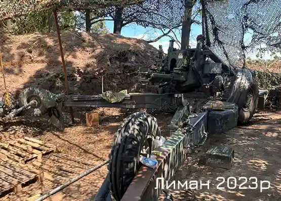
Calibrating the quadrant:
To calibrate the quadrant:
- Place the 155 mm FH-70 self-propelled towed howitzer on a hard surface, lower its support plate and raise the wheels.
FH-70 set on its
support plate (wheels raised)
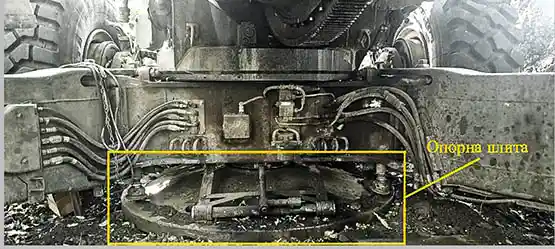 FH-70 set on its
support plate (wheels raised)
- Clean the leveling plates on the breech of dust and wipe them dry.
- Set the quadrant to 0-00, place it on the leveling plate across the barrel and level the howitzer using the hydraulic system (raising the right or left trail).
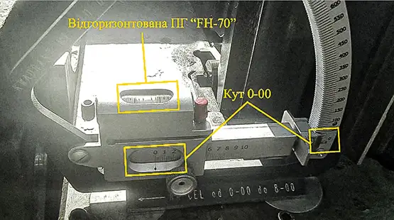
Placing the quadrant on the
breech leveling plate
- Place the quadrant on the leveling plate along the barrel and, using the elevation handwheel, bring the bubble to the middle (between the marks).
- Turn the quadrant through 180°. If the bubble is exactly in the middle, the quadrant is calibrated (the permissible error is no more than 1/4 of a division of the quadrant vial scale).
- If the bubble moves, part of the error is corrected with the quadrant stop screw and the remainder with the elevation handwheel, so that the bubble is centered.
- Repeat these steps until the bubble stops moving when the quadrant is turned through 180°.
Checking the sight zero settings: - First set the quadrant to 0-00. Then, with the quadrant placed on the leveling plates, level the howitzer barrel horizontally both longitudinally and transversely.
- Next, place the quadrant on the panoramic telescope seat face parallel to the longitudinal level. Turning the elevation handwheel, center the bubble on the quadrant.
- Turn the quadrant through 90° on the telescope face and, by turning the cross-leveling handle, center the bubble again.
- Then place the quadrant parallel to the longitudinal level again to check that the bubble has not drifted.
- After all these steps the sight scales should show zero settings, and the cross-level bubble of the sight should be exactly in the center.
- If the zero marks on the aiming mechanism scale do not coincide with the pointer line, undo the six hex screws that secure the setting ring and turn it until the zero mark of the scale lines up with the pointer line. Then tighten the screws again.
- If the cross-level bubble is not centered, adjust its position with the upper and lower adjusting screws. First remove the cross-level cover, then put it back after adjustment.
Checking the sight zero settings
Placing the quadrant on the face of the
panoramic telescope seat parallel to the longitudinal level
- Turn the quadrant through 90° on the telescope face and, turning the cross-laying mechanism handle, center the bubble again.
- Place the quadrant parallel to the longitudinal level again and check that the bubble has not shifted.
- After these operations the sight scales should show zero settings, and the cross-level bubble should be exactly in the center.
- If the sight scales do not coincide with the pointer line, undo the six hex locking screws that hold the setting ring. Then turn the ring so that the zero mark of the sight scale is opposite the pointer line, and tighten the screws.
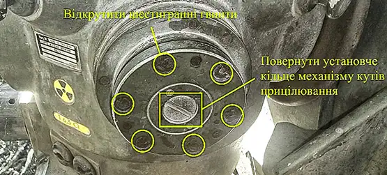
Setting ring for adjusting the mechanical sight scale readings of the FH70 sightZero mark of the sight scale set against the pointer line
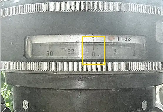 Zero mark of the sight
scale set against the
pointer line
- If the cross-level bubble is not in the middle, adjust its position with the upper and lower adjusting screws. To do this, remove the cross-level cover and put it back after adjusting.
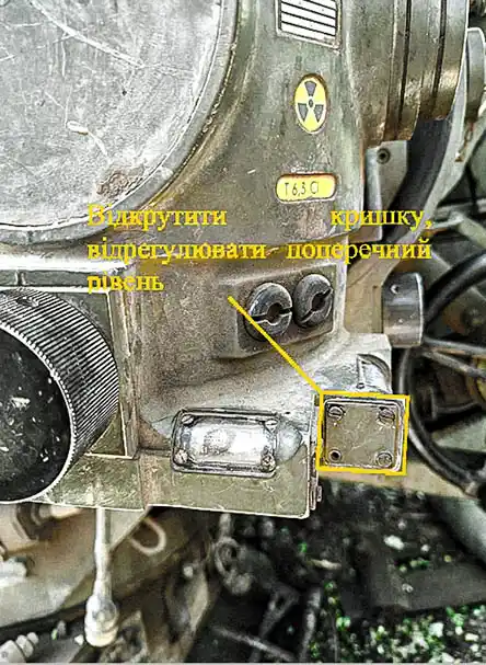
 Cross-level
adjustment
Cross-level adjustment
Threads stretched across the marks on the muzzle face of the barrel
- Remove the firing pin from the breech block.
- Align the hole in the breech block with the center of the thread cross on the muzzle face and lay the barrel on the aiming point (the distance to this point must be at least 1,000 meters).
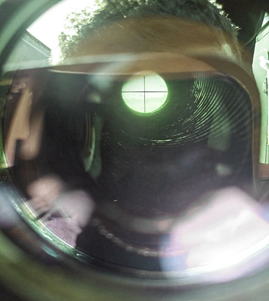
Laying the barrel on the aiming point through the hole in the breech block and the center of the thread cross on the muzzle face
- Level the sight with the cross-level and, turning the drums of the goniometer and the telescope reflector, align the panoramic telescope reticle (central angle) with the point on which the barrel is laid.
- As a result of these operations the scales of the panoramic telescope goniometer and reflector
should read 0-00
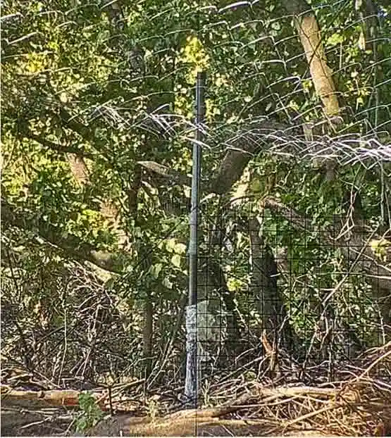
Laying the panoramic telescope on the aiming point
- If the goniometer and reflector settings are off by more than half a division, loosen the bolts on the goniometer drum with a screwdriver. Turn the graduated goniometer ring so that the zero marks coincide with the pointer marks, then tighten the bolts.
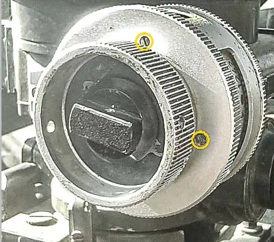
Goniometer drum bolts
See also:
Orienting the panoramic telescope to mils 64-00 using the PAB-2M aiming circle
Also on this site 

- Calibrating the sighting devices of the M109A3 howitzer
- How to enter the correction when firing illuminating projectiles
- Range tables for specific projectiles
- Why is it so important to fire at higher angles?
- Mortar-style firing: the effect of traverse on accuracy
- Cognitive information — all articles of the section
Orienting a 64-00 mils panoramic sight with the PAB-2M aiming circle
1. The preliminary setup and orientation of the PAB-2M aiming circle is no different from the usual one. We end up with the aiming circle pointed in the main direction of fire (MDF) and the angle-measuring (red) scales zeroed.
How to enter the correction when firing illuminating projectiles
During night combat operations, artillery units, in addition to fire missions to engage targets, perform the following tasks:
Why is it so important to fire at higher angles?
This material briefly explains how the projectile’s landing angle affects the effectiveness of engaging the enemy through fragment dispersion.
Oleh Syrota (Georgich©) for the Armed Forces of Ukraine /
Share your experience of working with 155 mm ammunition.
Send comments and suggestions by email: entropiaw@gmail.com
f FacebookKHMS 88
